
Programming an LED screen covers several distinct steps: hardware selection, cabling, software configuration, and content management. From the first connection to the first display, each step follows a clear logic: hardware selection, cabling, software configuration, and content management.
Architecture and Components of an LED Screen to Program
An LED screen follows a hierarchical architecture: LEDs form LED modules, modules integrate into cabinets or chassis structures to form the final LED display panel. Each level imposes its own cabling, LED control, and addressing constraints.
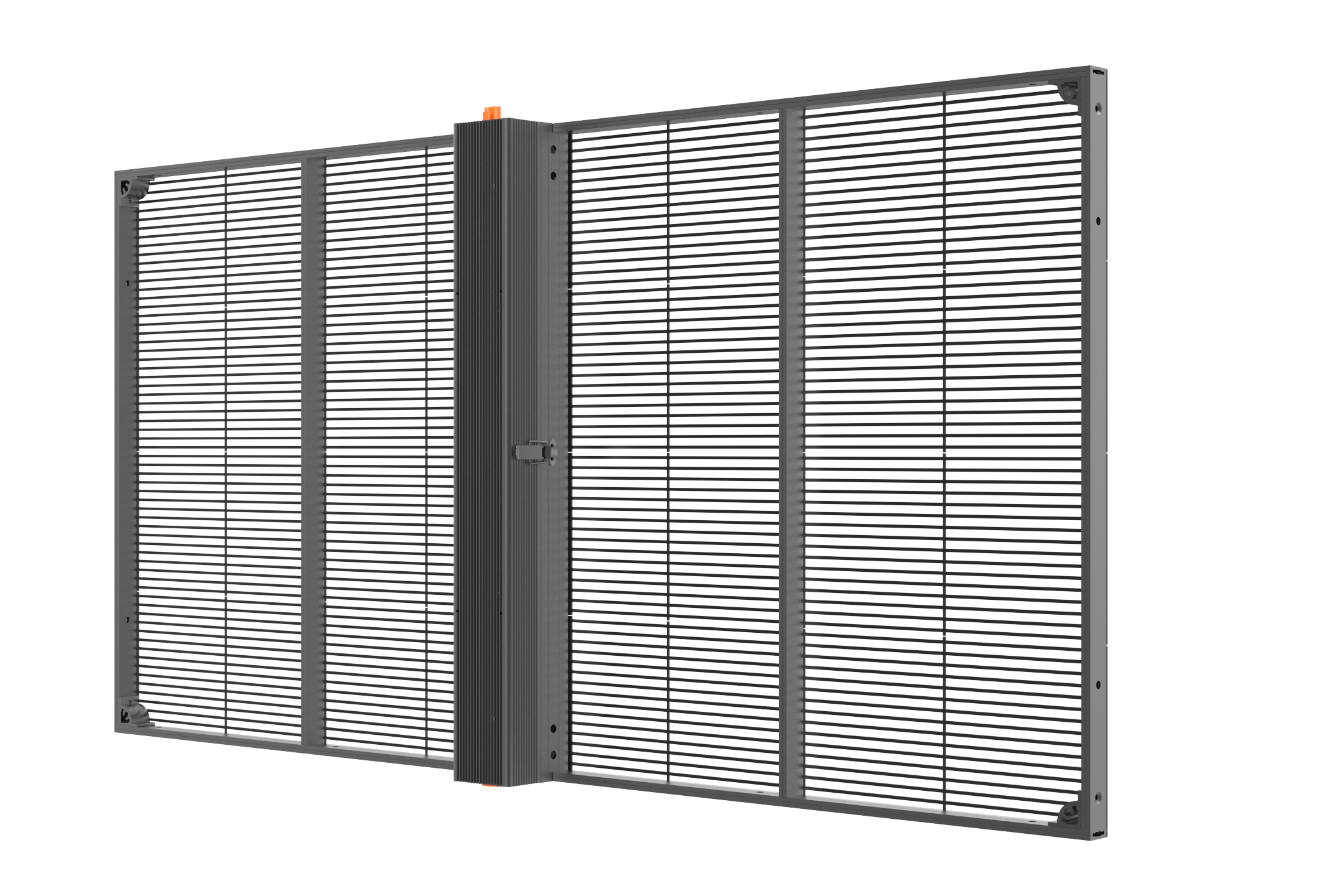
How Does a Programmable LED Display Panel Work
The operation of an LED screen relies on a precise chain. The source sends a video signal, the processor adapts it to the required resolution, and the data is then distributed to each reception card. From there, each module receives its instructions and the image is built pixel by pixel on the programmable LED display panel.
- Content source: computer, multimedia player or network feed responsible for producing the content to be displayed.
- Video processor / output box: the central element of the LED control system, it processes the video signal, adjusts the format and distributes data to the cards.
- Reception card: an interface installed within LED modules or nearby, it translates processor commands into actual LED driving.
This separation simplifies maintenance. If a reception card fails, intervention remains localized without calling the entire display system into question.
Pitch, Brightness and Hardware Selection for LED Entertainment Screens
Pitch, expressed in millimeters between two pixels, directly determines display quality based on viewing distance. For an LED entertainment screen installed in a large room, a P3.9 to P4.8 pitch remains suitable when the audience is more than 8 meters away. Conversely, a pitch that is too wide viewed up close reduces the readability of texts, logos and fine details.
Hardware selection also depends on the LED screen brightness and the installation context:
- P1.5: viewing distance of 0.5 to 1 m, very high pixel density, indoor use at very close range, higher cost.
- P1.9 to P2.6: distance of 2 to 4 m, commercial or event use, brightness between 500 and 1,200 nits indoors.
- P3.9 to P4.8: distance over 8 m, good readability on large surfaces, a common format for events.
- Outdoor: brightness of 4,500 to 5,000 nits, waterproof protection, UV and dust resistance are essential.
Power consumption follows this power level: between 120 and 200 W/m² in standard use, with peaks reaching 2,000 W/m² at full power under strong ambient light. The return on investment depends on this energy reserve as much as on the sizing of the electrical panel, which must be verified before installation.
Reception Cards and LED Data Flow
In a display system, multiple reception cards work in parallel. Each one drives a specific zone of the LED screen and processes its share of data sent by the processor. This organization prevents a local failure from cutting the entire LED display, while facilitating diagnostics, configuration and LED control operations.
A consistent distribution of cards, delimited zones, sequential addressing and software calibrated to the actual resolution minimizes artifacts and accelerates diagnosis in case of partial failure.
Physical Installation and Cabling Before Configuration
The stability of an LED screen is determined first on the ground. Even before opening the software, the screen installation must be clean, readable and secure: an undersized power supply, a reversed connection or a cable constrained at the wrong point will cause defects that no configuration can fix later.
How to Install a Flexible LED Screen Step by Step
Understanding how to install a flexible LED screen means adapting mounting methods to the actual surface: curved wall, suspended structure, mobile frame or freestanding solution. An LED screen installation designed for a non-flat surface is not handled the same way as a standard LED panel, and this initial choice conditions both mechanical integrity and the final output.
Scheduling also matters. Between ordering, component preparation, installation and commissioning, it takes an average of 8 weeks. This lead time should factor into project planning, especially when multiple stakeholders share the same technical area.
- Component check: inspection of each LED module, cable, LED panel and power supply before handling, with at least two qualified technicians for manual handling.
- LED module assembly: connection via Easy-Lock system, tool-free, to maintain alignment and overall rigidity.
- Configuration choice: wall mounting, suspension, mobile structure or freestanding based on site constraints and IP certifications required outdoors.
- Cabling preparation: upstream mapping of data and power conduits to avoid reversals during LED screen installation.
The Easy-Lock system saves time and reduces assembly errors during real installation. Once the structure is firmly mounted, cable routing becomes more readable and configuration can begin on a solid foundation.
For a custom project, programming an LED screen with expert support helps shorten the commissioning phase. This approach is ideal when lighting is part of the design, particularly on complex surfaces where installation precision directly affects display quality.
Data Cabling and Power Supply for LED TV Panels
Once the structure is in place, cabling becomes the priority. On an LED TV panel or any close-range indoor LED screen, image clarity depends directly on the data flow order: the route follows a zigzag pattern by columns, starting from the lower-left cabinet, through the DATA IN and DATA OUT ports of each LED module. The output depends on this continuity, since a single reversal can create dead zones or flickering.
Power follows a clear cascade: POWER IN on the first cabinet, then each POWER OUT connects to the POWER IN of the next. Depending on the site, the connection to the control system may use Ethernet, fiber optic, Wi-Fi or GSM. Unlike a lightweight temporary installation, a permanent installation requires a dedicated electrical panel with protections suited to the actual power consumption.
Post-Installation Tests and Verification
When cabling is complete, initial tests validate the installation before any software intervention. On the reception card, indicator lights provide a quick diagnosis: a steady or flashing red light confirms proper power, while its absence points to a rectifier fault or a socket to recheck. What matters visually is the final image: hardware checks therefore precede any software intervention.
- Power test: verify that all LED modules light up uniformly during the first power-on.
- White balance test: identify dead LEDs and color deviations before software configuration.
- Indicator reading: slow green blink: good reception of the video signal. Three green flashes followed by a pause: no video flux, configuration check needed.
- Data check: trace the route column by column to confirm data follows the intended path.
Once the installation is finalized and validated step by step, LED screen troubleshooting becomes faster, since the physical base, connection and video signal have already been methodically checked.
Software and LED Controller Configuration
Once the cabling installation is validated on the hardware side, software takes over. This is when the LED controller, control card and LED screen are aligned on the same configuration: resolution, module addressing and data flow. Proper tuning avoids image lag and stabilizes everything from commissioning.
Choosing and Installing the Right Programming Software
To program an LED panel, the choice of programming software depends first on the LED controller used, then on the level of customization desired for content, display settings and LED control.
On a 4x3 LED screen, very common in advertising displays, the exact pixel dimensions must be entered when creating the project in the software. A single incorrect value is enough to offset the entire image on the LED panel surface and skew subsequent settings. In real installations, this step conditions everything that follows.
Two references come up often: LEDStudio for generic systems, and Nova LCT for the Novastar ecosystem. These tools are provided via download or with the control card depending on manufacturers. From the first launch, default settings should be reviewed to avoid configuration conflicts between the computer, the LED controller and the LED screen.
For more experimental contexts or prototyping on small formats, Arduino offers unit LED control, custom scripts and rapid testing on simple content, a complementary logic to these professional tools, useful for validating a signal before moving to a larger installation.
| Software | Compatible Manufacturer | Key Features | Availability |
| LEDStudio | Generic controllers | Playlist management, text, images, video | Free download |
| Nova LCT | Novastar (MCTRL300…) | Color calibration, firmware management, RCG | Provided with the card |
| Arduino | Prototyping / small formats | Unit LED control, custom scripts | Open source, program Arduino LED |
| LCD via Arduino | LCD screens / small modules | Text display, minimalist interface | Open source, Arduino LCD program |
Novastar MCTRL300 Configuration and Essential Settings
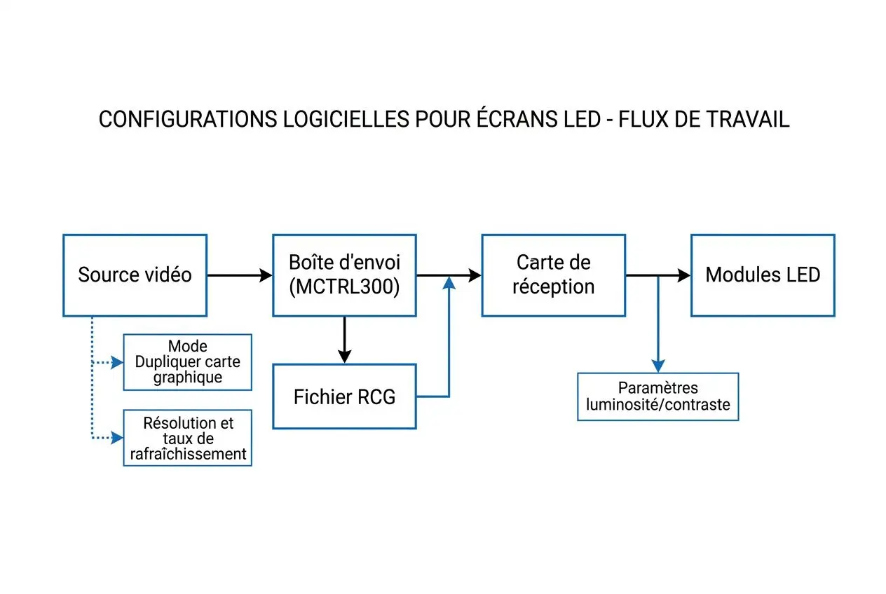
In the Novastar environment, the MCTRL300 remains a widely used control card. The associated software detects the card, loads the RCG file suited to the modules and allows adjusting the key LED screen settings. What the eye sees is image stability; this result depends on an exact correspondence between the RCG file and the installed hardware.
If this file does not match the modules, the display becomes inconsistent or disappears completely. Conversely, correct configuration restores normal behavior without heavy correction.
The most frequent point of vigilance concerns the computer. For the card to receive the video signal correctly, the graphics output must be set to “Duplicate” mode. In “Extend” mode, the LED screen may remain black even though data flows properly within the system.
Setting Resolution and Colors for a 4x3 LED Screen
Once communication is established, the work moves to the output. The video processor adapts the source resolution to the actual format of the 4x3 LED screen, then processes the color conversion to preserve visual consistency of the content. The output depends on these settings as much as on the LED screen brightness.
The parameters to always validate remain the same: resolution, contrast, brightness, refresh rate and video playback modes. A calibration performed at this stage limits display drift over time, especially when the installation runs for extended hours.
Once the installation is finalized, saving the configuration in the control card locks in the selected settings. Content can then be synchronized via the internet without manual intervention, provided the software, LED controller and input data remain consistent throughout the chain.
Content Management and LED Display Troubleshooting
Once the hardware and software configuration is validated, content management on the LED screen becomes the core of the setup. The operation of an LED screen no longer depends solely on installation or cabling: the displayed content, its broadcast rhythm, effects and scheduling settings directly influence readability and visual impact of the LED display.
Programming and Broadcasting Content on Your LED Screen
With this foundation in place, content must be designed according to the surface size and reading distance. LEDStudio software centralizes this configuration from a computer connected to the system: it allows importing videos, images, texts and animations, then structuring content into playlists ready for real-time playback. Once the installation is finalized, brightness and display duration adjustments are made from the same interface, avoiding scattered fixes from station to station.
- Small screens: short videos and image sequences favor immediate reading on a reduced surface.
- Large formats: large-body text and Full HD graphics maintain readability at long distance.
- Remote management: a media player enables switching between sources and network or GSM card broadcasting without physical on-site intervention.
Once multiple units are deployed, internet connection simplifies updates. Online synchronization pushes content modifications across the entire fleet in a single operation, where a manual method requires visiting each screen individually.
Effects, Scrolling Text and Advanced Content Installation
In the software, text programming goes through the Text tab: content is entered, formatted, then sent to the controller via the Send tab. Parameters are stored in this controller even without an active USB connection, securing daily broadcasting.
- Revision: adjusts text appearance, with font, size, color and alignment.
- Time / Clock: adds a real-time clock or calendar to the composition.
- Counter: integrates a customizable countdown, useful for events.
- Hypertext: inserts images within a text stream.
For scrolling text, the choice of font, number of lines and scroll libraries directly affects perceived fluency. If the refresh rate is too low, judder becomes immediately visible regardless of viewing distance.
Diagnosing and Correcting Common Display Failures
When an LED screen stays black, three points should be checked first: a failing power supply, a poorly plugged cable or a misconfigured reception card. In real installations, this method prevents launching heavy electronics interventions too early.
Flickering often comes from the data connection. Replacing it with a properly shielded quality cable, or reducing network length, generally restores a stable display. On the firmware side, three green flashes followed by a pause signal a pending update, while a very fast green blink indicates a fault requiring a new flashing procedure.
When defects exceed 5% of the total surface, replacing the panel is often more practical than multiplying repairs on dead pixels or defective circuits. A semiannual calibration compensates for the natural chromatic drift of blue and red diodes, visible especially on whites and neutral tones. With proper maintenance, an installation can exceed 100,000 hours of service.
FAQ: Frequently Asked Questions
How to program an LED screen without advanced computer skills?
A software like LEDStudio guides the configuration step by step: LED screen dimensions in pixels, loading the RCG file suited to the control card, then verifying the connection with the video source.
Next, the critical point concerns the display of the PC controlling the LED control. The graphics card must be set to “Duplicate” mode so the video signal is sent correctly to the LED control system. Once the installation is finalized, content synchronization can be done via the internet without heavy technical intervention.
For simple use on small formats, an Arduino solution remains relevant. With basic tools, a suitable power supply and a clear tutorial, this control card allows programming basic LED sequences without entering complex development logic.
What are the signs that the LED control system configuration is incorrect?
The first indicators often come from the indicator lights and image behavior. Three green flashes followed by a pause indicate that the LED control system is running but receiving no video signal: you should then check the software settings, the physical connection and the video source output.
Conversely, a very fast green blink points to a firmware update fault. If the LED screen stays black despite proper power, the cause often lies in the PC display configuration: “Extend” mode instead of “Duplicate”, or brightness set to zero in the software.
In this case, verification should follow a simple order: first the control card, then display settings, then the content sent to the LED control. In real installations, this method avoids looking into cabling when the blockage comes only from a software setting.
What is the difference between indoor and outdoor LED screens for programming?
The programming logic remains the same: tools, software and control card follow the same principles, whether for an indoor or outdoor LED screen.
The difference appears in environment-related settings. Outdoors, brightness generally needs to be set between 4,500 and 5,000 nits to keep content readable in full sun, compared to 500 to 1,200 nits indoors: the output depends on the actual site exposure.
Once the installation is exposed to light variations, sensors allow automatic intensity adjustment. This management reduces consumption by up to 40% depending on sunlight. A programmed night shutdown between 11 PM and 6 AM can also generate an estimated savings of 330 to 660 EUR per year, depending on the installation surface.