
Common LED video wall problems span a wide spectrum: faulty pixels, black screens, flickering, overheating, brightness loss, or desynchronization. This guide provides a clear diagnosis of each malfunction to help you restore stable, readable, and accurate LED display performance.
Faulty Pixels on an LED Display
An LED display showing black spots or dead zones loses readability immediately. The defect may stay limited to a few diodes, or affect an entire module, or even a full LED panel depending on the root cause. The key is measuring precisely how widespread the failure is before intervening.
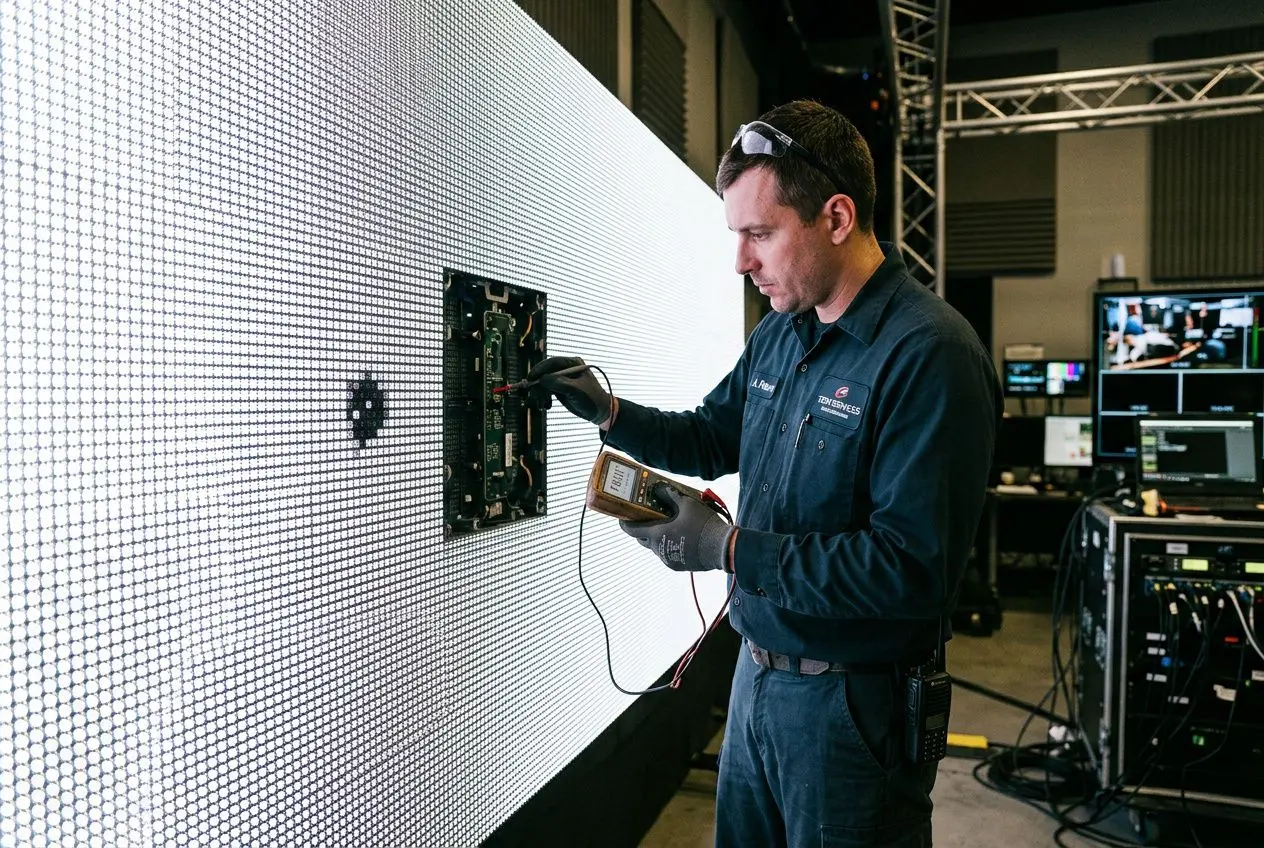
Identifying dead pixels on an LED display
Pixel issues on LED screens are first spotted with a uniform white test pattern: dark areas appear immediately. Once this initial check is done, mapping software pinpoints every anomaly, module by module, targeting the right zone without unnecessary disassembly.
- Mapping software: provides a precise view of every faulty pixel to prioritize which modules need inspection.
- Module-by-module testing: checks driving circuits and the connection of each element.
- Interconnection verification: data link checks remain essential, especially on large modular surfaces.
- Protective coating inspection: degraded protection accelerates the appearance of visible defects over time.
Repairing or replacing a faulty LED module
When the malfunction stays localized, reactivation can be attempted before replacing the part. Very gentle pressure with a microfiber cloth may sometimes restore an unstable connection, while a specialized tool sends a targeted electrical pulse to the affected circuit.
- Electrical stimulation: useful when the failure comes from a temporary electrical defect rather than a permanently blown diode.
- Multimeter: checks continuity and confirms which module needs replacing.
- Partial replacement: makes sense if the affected area represents less than 5% of the total surface.
- Full panel replacement: becomes more cost-effective beyond 5%, especially if defects reappear after intervention.
The outcome depends on how regularly checks are performed: preventive monitoring catches display issues before they become visible to the public. For a more complete approach to LED display problems, combine visual inspection with electrical measurements.
Preventive maintenance to minimize LED pixel problems
A clean surface ages better. Monthly dry microfiber cleaning is generally sufficient to preserve modules without damaging diodes or protective coatings. Once dust accumulates around components, it can disrupt sensitive connections and encourage localized defects.
Similarly, inspecting power cables, connectors, and the general power supply remains essential. Vibrations, temperature fluctuations, or tight installations can introduce mechanical play in these elements; proper tightening stabilizes the image and prevents intermittent issues ranging from partial black screens to flickering.
After final installation, periodic calibration preserves visual balance. LEDs do not age at the same rate, and color brightness can drift over time. This is particularly relevant where light is part of the decor: calibration avoids confusing gradual chromatic drift with actual malfunction.
A breakdown is not always linked to the module itself: unstable power, poor connections, or progressive wear can be enough to degrade LED display quality. In practice, systematic maintenance reduces display issues, secures critical connections, and limits the appearance of defective pixels.
Power and Cooling of an LED Display
The power supply determines the stability of an LED display system. When it fluctuates, the impact is immediately visible on brightness, display continuity, and color consistency. Thermal management follows the same logic: if heat is not properly dissipated, components age faster and defects appear sooner.
Power supply failures and their effects on LED display
A blown fuse, faulty transformer, or voltage spikes can cause black screens, repeated cutouts, or intermittent operation. These failures are often mistakenly blamed on software or the control system when the root cause lies upstream. An unstable power supply also disrupts system cooling: power blocks overheat more, intensifying malfunctions over time.
This electrical instability often manifests as irregular brightness from one module to the next, sometimes accompanied by visible flickering. Overvoltage accelerates diode wear. Undervoltage creates dark zones without any physical LED failure. For a useful diagnosis, checking the power supply with a multimeter or network analyzer is always the first step of any maintenance.
Preventing overheating to avoid LED display problems
When internal temperature rises too high, thermal protection cuts power to preserve the LED display. In real installations, this is one of the most common causes of unexpected shutdown on a continuously running video display system.
Proper thermal management can extend LED lifespan by 30 to 40%, but the result depends on actual air circulation around the modules and the requested brightness level.
- Cleaning ventilation grilles: removing accumulated dust on fans improves airflow and reduces internal temperature.
- Side clearance: maintaining at least 10 cm of clearance on each side limits hotspots and promotes more even cooling.
- Brightness capped at 80%: reducing the maximum level cuts heat output and long-term stress on the power supply and display components.
In confined installations — backstage areas, columns integrated into walls, or low ceilings — supplementary active cooling often becomes necessary. A dedicated fan or targeted air conditioning helps maintain a temperature compatible with stable operation. The technical guide on lighting and ventilation published for educational establishments highlights the importance of controlled ventilation in any space housing continuously operating electronic equipment.
A stable electrical source and consistent heat dissipation enable exceeding 100,000 hours of operation under good conditions. Without this foundation, flickering, black screens, or repeated shutdowns will return recurrently.
Cabling, Signal, and LED Display Synchronization
On an LED video wall, the signal chain starts at the source, passes through the control card, then the receiving card before reaching the modules. This is often where the most troublesome incidents concentrate: faulty cables, oxidized connectors, or misconfiguration can cause signal loss, flickering, or complete display failure.
Cables and connectors as common display problem sources
Cable-related display issues rarely manifest stably. The image appears then disappears, a segment of the LED video wall freezes, or artifacts vary depending on cable position: in real installations, this intermittent behavior almost always points to connectors, pins, or the cable itself rather than a clear module defect.
The first useful step is temporarily replacing the suspect link with a quality shielded cable. This quick check rules out simple causes before intervening on cards or system parameters.
- Shielded replacement cable: testing with a quality shielded cable immediately isolates whether the problem is the faulty cable or an active component.
- Pin inspection: checking the integrity of HDMI, DVI, and RJ45 pins, and the absence of oxidation on contacts, ensures correct signal transmission.
- EMI shielding: unshielded cables running near high-voltage power lines pick up interference that triggers random restarts and flickering.
This verification logic extends to the cards. The LINK and ACT indicators on the control and receiving cards provide a first-level reading: an unusually slow ACT light can signal signal loss on the network before even opening the enclosure. Beyond that, distance remains a real constraint: without an intermediate repeater, qualified network cables should not exceed 100 meters to preserve LED display stability.
Added to this distance constraint is the choice of transmission medium. For network links exposed to a dense technical environment, category 6A shielded twisted-pair cables provide a more reliable margin, especially if physical separation from power lines is maintained. The outcome depends on the quality of the received signal, not just the installed panel.
Resolving synchronization conflicts on an LED video wall
Once signal transport is reliable, LED display synchronization becomes the primary concern. When multiple sources, multiple output cards, or multiple broadcast zones coexist, errors can appear: horizontal tearing, video stuttering, capture flickering, or an overall unstable display impression.
The most frequent cause remains a mismatch between the LED refresh rate, the source frequency, and sometimes the camera frequency. If these cadences are not aligned, the LED video wall can deliver erratic output even when no module is actually failing.
The stroboscopic effect occurs when the camera captures the panel’s on/off cycles. The moiré pattern, conversely, is not a failure but an interaction between the sensor and the pixel grid. A slight distance change or small angle adjustment often reduces these visual artifacts without modifying the hardware configuration.
| Symptom | Probable cause | Corrective action |
| Horizontal tearing | Inappropriate refresh rate | Align source and display refresh rates |
| Stroboscopic effect | Camera-LED wall desynchronization | Match camera frame rate to wall frequency |
| Visible moiré | Sensor-pixel grid interference | Slightly adjust camera distance or angle |
| Blurry or compressed image | Source resolution exceeds display resolution | Reduce source video resolution |
Resolution must be examined alongside synchronization. A source set beyond the LED video wall’s native resolution forces resizing, resulting in a blurry, compressed image and sometimes additional synchronization errors. The outcome depends on the match between the video output, processor, and actual screen matrix.
Control card configuration and firmware
When cabling is sound and LED display synchronization remains unstable, revisit the internal configuration. The receiving card applies parameters that define brightness, refresh rate, gray levels, and module mapping. Widespread color issues, offset zones, or inconsistent display usually point to misconfiguration rather than a physical LED display failure.
Consistency between the control card, receiving card, LED control software, and firmware is critical. Mixed versions produce conflicting data reads, leading to either immediate or progressive malfunction.
- Version uniformity: different receiving card versions on the same LED display cause abnormal display; all must be updated to the same level before reloading the configuration file.
- Firmware updates: a rapidly blinking green indicator signals a firmware update failure; re-launching the procedure from the manufacturer’s official site resolves the issue in most cases.
- Software reinstallation: for persistent control system malfunctions, completely uninstall the software, restart, then reinstall from the official source to eliminate configuration corruption.
After final installation, processor video output remains the last point to validate: the output width must exactly match the LED display’s pixel width, and the height its native definition. Beyond even a small margin, forced resizing reintroduces some of the defects corrected upstream, particularly on edges and motion stability.
Stability ultimately depends on the electromagnetic environment. Compliance with European LED wall standards governs equipment compatibility, limiting interference and securing signals in spaces with high technical density.
LED Display Maintenance and Lifespan
The lifespan of an LED video wall depends not only on initial quality. It also depends on power supply stability, heat dissipation, and the regularity of maintenance carried out during operation. In real installations, an LED screen with little monitoring ages significantly faster than one maintained according to a precise schedule.
Maintenance routine for optimal LED display
LED display maintenance works best when organized across three rhythms: monthly, quarterly, and semiannual. A dry microfiber cloth is sufficient each month to remove dust without fragilizing LED modules. This simple cleaning is especially useful in environments where particles accumulate quickly, as they hinder ventilation and encourage localized heating.
On top of this first level, technical inspections are needed. Every three months, inspecting connectors and power cables anticipates loosening, oxidation, or mechanical fatigue that will eventually disrupt a LED panel’s power supply. Every six months, recalibration compensates for the natural drift of certain diodes to preserve uniform output across the entire LED video wall.
This preventive logic produces measurable results. In professional settings, available data shows that regular maintenance can reduce pixel failure rates by up to 60%. The difference comes down to integration: documented monitoring enables comparing differences over time, spotting slow drifts, and intervening before one module affects the entire display.
Signs of wear and planning for replacement
LED modules generally reach 50,000 to 60,000 hours of operation, and more when cooling remains effective and shutdown cycles allow components to cool down. In the best-managed installations, nightly shutdown for several hours helps approach or even exceed 100,000 hours. This theoretical duration remains tied to operating conditions: ambient temperature, brightness level requested, and electrical power quality.
- Persistent brightness drop: an approximate 30% loss despite maximum setting indicates advanced diode aging and points toward targeted replacement.
- Yellowish tints: if color drifts remain visible after calibration, the LED panel is often near the end of its cycle.
- Excessive heat to the touch: an abnormally warm surface, even after cleaning the ventilation, may signal power block or LED module fatigue.
These signs typically appear after 8 to 10 years of intensive use, sometimes subtly: the difference is hard to perceive without side-by-side comparison, making early diagnosis all the more valuable. The outcome depends on diagnosis speed: the earlier the difference is spotted, the simpler and more localized the intervention remains. In a hallway, storefront, or control room, this timing directly changes operating costs and service continuity.
When an LED display does not function as expected, act before complete failure. Preventive replacement of the most stressed zones limits operational interruptions and preserves the visual coherence of the LED video wall. Stable power, regularly checked connectors, and documented maintenance prolong the reliability of the LED video wall for years.
Frequently Asked Questions
What is the lifespan of a properly maintained LED video wall?
A properly monitored LED video wall remains in service for more than ten years in most uses. LED modules are generally rated for 50,000 to 60,000 hours of standard operation, with potential that can exceed 100,000 hours when thermal management is controlled, power remains stable, and preventive maintenance is planned.
The actual duration then depends on the usage rhythm. Turning an LED screen off for several hours daily limits thermal stress and slows component wear: in real installations, it is often these simple settings that most noticeably extend the lifespan.
How do I diagnose an LED screen that shuts off on its own with no apparent reason?
Repeated spontaneous shutdown most often signals overheating. The first check focuses on the immediate environment: clean ventilation grilles, at least 10 cm of side clearance, and keeping brightness below 100% over extended periods.
If the cutout continues, trace the electrical chain. A blown fuse or faulty transformer in the power supply can cause the shutdown, while the receiving card’s indicators verify whether power and connection signals are properly detected by the system.
Why do incorrect color zones appear on an LED video wall?
A localized color issue often comes from a weakened diode in a pixel. Each pixel on an LED video wall relies on three diodes — red, green, and blue — and when one component drifts, the displayed color becomes inconsistent.
Conversely, a larger zone points to oxidation or a loose connector: disconnecting and reconnecting the affected module often restores the display. A semiannual calibration then corrects natural chromatic drift. If several LED modules display erratic colors simultaneously, check the configuration file and reload it from the control software, as the output depends on this setting.